METHODOLOGY FOR QUANTITATIVE RISK ASSESSMENT (QRA) STUDY
Proposed Methodology
1. Introduction
QRA is a technique used to systematically calculate the risks from hazardous events. It involves predicting the size of consequences associated with a hazard, and the frequency at which a release of the hazard may be expected to occur. These aspects are then combined in order to obtain numerical values for risk – usually risk of fatality.
QRA includes consideration of all identified hazardous events in order to quantify the overall risk levels. Similar hazardous events are often grouped and assessed together as bounding or representative events.
2. Methodology
The QRA Study included the following steps:
Identification of Hazards (Fire / Explosion / uncontrolled release of Hazardous material/ Flash Fire / Jet Fire / Vapor Cloud Explosion (VCE) Unconfined Vapor Cloud Explosion (UVCE), etc.)
Identification of Maximum Credible Accident (MCA) scenario.
Frequency Analysis using an internationally accepted database and Evaluation of the likelihood of occurrence of possible events.
Consequence modelling and analysis for the identified hazard covering impact on people and potential escalation by using PHAST (process hazard analysis software tool) Risk
Estimation of Individual Risk (IR) and Societal Risk (SR)
Recommendations.
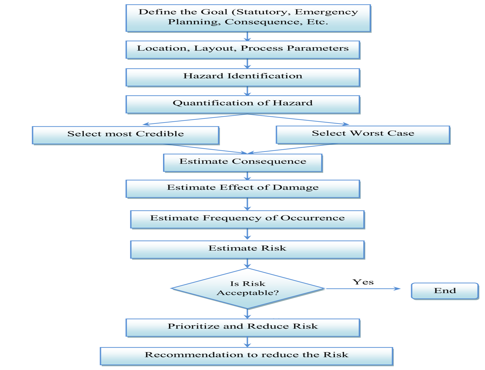
Figure 1:QRA Methodology Flow sheet
3. Hazard Identification
The hazardous scenarios considered in the QRA for the project facility will be identified based on the properties of the materials handled and the identification of the potential hazards in the pipeline systems which could lead to loss of containment events.
4. Consequence Analysis
The following activities comprise the consequence analysis which is carried out for the project facility:
Review of the P&ID’s to determine process streams;
Identification of isolatable sections based on the location of Shutdown Valves;
Review of the design basis to obtain the properties of the stream (e.g. pressure, temperature, composition and density) and
Calculation of the inventory within the isolatable sections.
Consequence modelling is conducted to evaluate the effect distances of the identified Loss of Containment (LOC) scenarios and their impact on people. This consequence analysis will be carried out using PHAST 6.7 software.
5. Frequency Analysis
Once the potential release scenarios are identified, the next stage is to estimate the failure frequencies (likelihood for the event to occur) based on international standard databases.
The frequency analysis will be performed as follows:
Identification of the base failure frequencies applicable to the product pipelines from the relevant international standard databases;
The total failure frequencies will be derived from the combination of the time in use factor of the pipelines/tanks with the base failure frequency data.
6. Risk Assessment
Risk assessment will be undertaken to evaluate the risk associated with the project facilities. The consequence analysis results and failure frequencies will be combined using PHAST RISK 6.7 software. The risk shall be typically presented as Location Specific Individual Risk (LSIR) contours overlaid on a map and Individual Risk Per Annum (IRPA).
7. Risk Evaluation
It involves the evaluation of the individual risk results against the UK HSE Risk Acceptance Criteria to determine whether the risks are broadly acceptable, ALARP or unacceptable and to make some professional judgements about the significance of the risks.
8. Risk Reduction Measures
Based on the risk evaluation, if the calculated risks fall in the unacceptable region or in the ALARP region, risk reduction measures shall be implemented in order to reduce the risk to a tolerable or ALARP region. All physically possible risk reduction measures shall be identified, which could be new measures or improvements to existing measures already installed/ implemented. The risk evaluation after implementation of recommendation/ risk reduction measures shall be carried out to demonstrate that the risk shall be reduced to the ALARP region and the study recommendations are adequate for the project.
9. Consequence Analysis
This section describes the approach used for the consequence analysis whereby consequence models are built based on the identified LOC scenarios of the project facility. The consequences of the release of hazardous substances by failures or catastrophes as well as the damage to the surrounding area can be determined by means of consequence modelling. Models help to calculate the physical effects resulting from a release of hazardous substances and help to translate the physical effects in terms of injury or fatality to the exposed personnel.
The techniques used to model the consequences of the hazardous material releases cover the following:
Modelling of discharge rates when holes develop in pipeline systems.
Modelling of the flammable clouds from releases to the atmosphere.
Modelling of the heat radiation field of the releases that are ignited and burn as jet fire and flash fire.
Modelling of explosion overpressure from releases.
10. Consequence Modelling
Discharge Rate
The initial rate of release through a leak depends mainly on the pressure inside the equipment, size of the hole and phases of the release (liquid, gas or two phase). The release rate decreases with time as the equipment depressurizes. The reduction mainly on the inventory and the actions taken to isolate the leak and blow-down the equipment
Dispersion
A vapour cloud may be formed when a vaporizing liquid is released for an extended duration. If the gas cloud does not immediately ignite, it disperses based on the prevalent wind direction, speed and stability category (i.e. degree of turbulence).
The cloud dispersion simulation is carried out to provide the distance (from the leak) at which the concentration of flammable material falls below the Lower Flammability Limit (LFL).
Consequence Events
The following describes the probabilities associated with the sequence of events which must take place for the incident scenarios to produce hazardous effects. Considering the present case, the outcomes expected are:
Flash Fire (FF);
Jet fires;
Pool fire;
Vapour Cloud Explosion
Flash Fire
The vapour/gas release from a pool would disperse under the influence of the prevailing wind; with material concentration in air reducing with distance. At a particular location downwind, the concentration will drop below its lower flammable level (LFL) value. If ignited within the flammable envelope, the mass of the material available between the LFL and ½ LFL will be likely to burn as a flash fire; rapidly spreading through the cloud from the point of ignition back to the source of release.
Although flash fires are generally low intensity transitory events, the burning velocity is quite high and escape following ignition is not possible. Flash fires often remain close to the ground, where most ignition sources are present. It is assumed that personnel caught inside a flash fire will not survive while those outside suffer no significant harm. If other combustible material is present within the flash fire it is also likely to ignite, and a secondary fire could result.
Jet Fire
Jet fire causes damage due to the resulting heat radiation. The working level heat radiation impact will vary widely depending on the angle of the flame to the horizontal plane, which in turn mainly depends on the location of the leak. The flame direction was considered horizontal for consequence analysis of leaks and ruptures from process equipment. Jet fire heat radiation impacts were estimated for the identified credible and worst-case scenarios.
Upon accidental leakage, the pressurized fluid will disperse as a jet, initially moving forward in the spatial direction of the leak until the kinetic energy is lost and gravity slumping or lifting of the cloud occurs, dependent upon whether the fluid is heavier or lighter than air.
The primary hazard associated with jet fires is thermal radiation and potential for flame impingement on adjacent pipelines/equipment, resulting in escalation. High pressure releases have the potential to cover large areas due to its relatively large flame length. However, the effects of escalation are minimized if the flame length reduces to less than the separation distance between other equipment and the jet fire source.
Pool Fire
A liquid pool is formed during a prolonged leakage if the rate of leakage exceeds the rate of vaporization. On ignition, this would result in a pool fire whose size/radius would depend on the mass flow rate, ambient temperature, heat of vaporization of material released, vapour pressure, duration of discharge and effects of containment or dykes. The pool fire could cause damage to equipment or injury/fatality to personnel due to thermal radiation effects.
A pool fire is not envisaged for liquid systems that are highly pressurized. Any leak or rupture would result in a pressurized release leading to a liquid jet fire or flash fire.
Vapour Cloud Explosion
Vapour cloud explosion is the result of flammable materials in the atmosphere, a subsequent dispersion phase, and after some delay an ignition of the vapour cloud. Turbulence is the governing factor in blast generation which could intensify combustion to the level that will result in an explosion. Turbulence is often created by obstacles in the path of vapour cloud or when the cloud finds a confined area, as under the bullets. Insignificant level of confinement will result in a flash fire. The VCE will result in overpressures.
11. Selection Of Damage Criteria
The damage criteria give the relation between the extents of the physical effects (exposure) and the effect of consequences. For assessing, the effects on human consequences are expressed in terms of injuries and the effects on equipment / property in terms of monetary loss.
The effect of consequences for explosion or fire can be categorized as:
Damage caused by heat radiation on material and people
Damage caused by explosion on structure and people
In Consequence analysis studies, three types of exposure to hazardous effects are distinguished:
Heat radiation due to fires - in this study, the concern is that of Jet fires and pool fires
Explosions
Toxic effects from toxic materials or toxic combustion products.
The knowledge about these relations depends strongly on the nature of the exposure.
Following are the criteria selected for damage estimation:
Heat Radiation
The effect of fire on a human being is in the form of burns. There are three categories of burn such as first degree, second degree and third-degree burns. The consequences caused by exposure to heat radiation are a function of:
The radiation energy onto the human body [kW/m2];
The exposure duration [sec];
The protecting layer of the skin tissue (clothed or naked body).
The limits for 1% fatality to the people exposed by heat radiation, and for second-degree burns are given in the table below:
Table 1 : Damages to human life due to heat radiation
Table 2 : Effects due to incident radiation intensity
Reference: CCPS, Guidelines for Chemical Process Quantitative Risk Analysis. The actual results would be less severe due to the various assumptions made in the models arising out of the flame geometry, emissivity, angle of incidence, view factor and others. The radiation output of the flame would be dependent upon the fire size, extent of mixing with air and the flame temperature. Some fraction of the radiation is absorbed by carbon dioxide and water vapor in the intervening atmosphere. Finally, the incident flux at an observer location would depend upon the radiation view factor, which is a function of the distance from the flame surface, the observer’s orientation and the flame geometry.
Table 3 : Damage due to overpressures
Some chemicals will have detrimental impact on humans and animals if inhaled. Effects of toxic chemicals are measured by IDLH, ERPG, STEL etc.
12. PROBABILITIES
Population Probabilities
It is necessary to know the population exposure to estimate the risk resulting from an incident. The exposed population is often defined using either a population density or population data.
Failure Probabilities
This step deals with determining how often – in terms of frequency per year – loss of containment events is likely to occur. The likelihood of occurrence of identified hazardous scenarios is assessed by reviewing the historical industry accident data.
Weather Probabilities
The weather and wind data considered will be either provided by client or will be taken from local meteorological center.
Risk Calculation
This step involves calculating risk considering both severity of the consequences of an identified hazard and the probability of its occurrence
Risk = Likelihood of Occurrences X Severity of Consequences
Risk is calculated using software SAFETI by DNV. The software takes the input from Frequency Analysis and Consequence Assessment Tasks. Risk is presented numerically and graphically.
Risk Assessment
This step deals with comparing the calculated risk with the acceptable risk values.
13. Consequence Contours
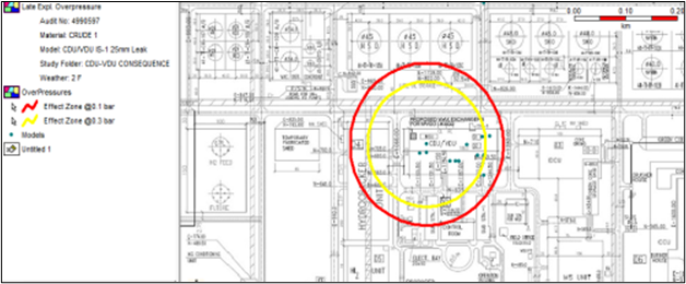
Figure 2: Medium Leak Explosion Effects
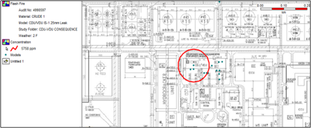
Figure 3: Medium Leak Flash Fire
14. Report
The methodology, study findings and recommendations from the QRA study will be presented in a comprehensive report.
Information Required
1. Plot Plan/Layout (with scale)
2. Piping and Instrumentation Diagrams (P&IDs)
3. Piping general assembly drawings
4. Aerial snapshot of site (preferably high resolution) or Google Earth coordinates
5. Facility Description
6. Operating Manual
7. Heat & Mass balance Sheet
8. Process Description
9. Process Flow Diagram
10. Cause and Effect Diagram
11. Emergency Shutdown Philosophy
12. Population Details (Location and Number)
Onsite Population
Offsite Population (Public)
13. Site Meteorology
Wind speed and direction
Atmospheric stability conditions
14. Ignition sources
Onsite and Offsite ignition sources
15. Other Information
History of Past Accidents and near misses
OLD QRA Report if any
Old HAZID / HAZOP Report
15. Guideline Used for QRA Study
TNO PURPLE Book
16. Software to be used
PHAST V 8.2 & SAFETI V 8.2 FOR CONSEQUENCE AND RISK ESTIMATION
17. Documents Deliverables
EXECUTIVE SUMMARY
INTRODUCTION
STUDY SCOPE OF WORK
OBJECTIVES OF THE STUDY
ABOUT THE SOFTWARE
FACILITY DESCRIPTION
OVERVIEW OF RISK ASSESSMENT
QRA METHODOLGY
HAZARD IDENTIFICATION
INVENTORY ANALYSIS
FREQUENCY ANALYSIS
EVENT TREE ANALYSIS (ETA)
IGNITION PROBABILITIES
CONSEQUENCE ASSESSMENT
SELECTION OF DAMAGE CRITERIA
Risk Assessment
WINDROSE
HAZARD IDENTIFICATION
Materials Properties
Dyke Details
FREQUENCY ASSESSMENT
PES MARKUP
PROCESS RISK ASSESSMENT
Location Specific Individual Risk
Individual Risk Per Annum (IRPA) and Potential Loss of Life (PLL)
PLL Calculations
SOCIETAL RISK
CONSEQUENCE RESULTS
Fire and Explosion Results
Exceedance Curves:
MAJOR RISK CONTRIBUTORS
CONCLUSION AND RECOMMENDATION
LIST OF ANNEXURES]
REFERENCES
Annexure-01 Assumption Register
Annexure-02 Isolatable Section Marked P&ID
DISCLAIMER
HSE Risk Management Services Private Limited accepts no liability or responsibility whatsoever for it in respect of any use of or reliance upon this Methodology by any third party.
Copying this Methodology without the permission of HSE Risk Management Services Private Limited is not permitted.


